FilterMax IV Instructions
Before you begin
Installing and configuring the FilterMax IV is a simple process which involves connecting the unit to your radio. You will need a length of 50 ohm coax with PL-259 connectors (not supplied). If you are using a ShackLAN equipped band decoder, such as the Array Solutions Bandmaster 3, any Hamation decoder or Integrated Controller, automatic band selection is as simple as plugging in a network cable between the FilterMax IV and the decoder. No other connections are required. For stand-alone operation or use with a non-ShackLAN equipped band decoder you will also need to connect the unit to a +12vdc power source. Control from an external device is done via the Remote connector on the rear panel. Apply +12v to the pin for the desired band selection. Connector pinouts are engraved on the rear panel for easy reference. Installation steps are listed below.
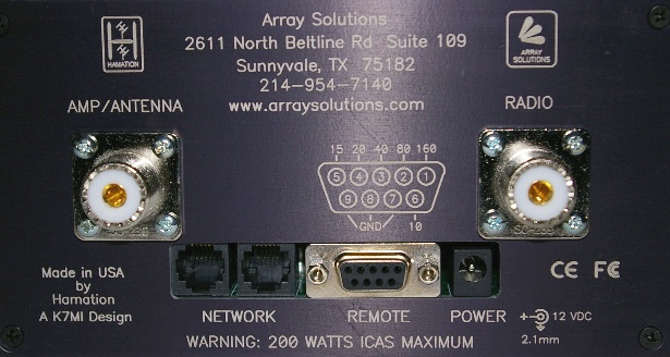
FilterMax IV rear panel
WARNING: The FilterMax IV is designed to be installed between your radio and amplifier. If you install the filters on the output of your amplifier, the filters will be destroyed the first time you transmit through them.
Installation
Power connection
A power connection is only required when operating the FilterMax IV stand-alone or with a non-ShackLAN equipped band decoder. Power requirements are +12-14vdc at 150 ma. The Power connector is a standard 2.1mm jack with the center pin positive. No power connection is required when operating with a ShackLAN equipped decoder as power is distributed over the network cables. A power cable is included with the unit. The wire is the white band is positive and the solid black wire is ground.
Network connection (ShackLAN)
Connecting the FilterMax IV to a ShackLAN equipped band decoder is done by simply plugging a 6-conductor modular cable from one of the network jacks to the decoder. Older decoders use a 4-pin screw terminal connector and an adaptor is available to facilitate operation with older decoders. Two network jacks are provided to allow easy daisy-chaining of other ShackLAN units. The two jacks are connected in parallel internally and either may be used.
External control wiring
 This step can be skipped if controlling the FilterMax IV with a ShackLAN
compatible band decoder or only with the front panel controls. For
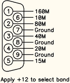
external control you need to apply +12v to the pin on the Remote
connecter for the desired band. Current required for each band is 150
milliamps. The pinouts of the Remote connector are shown to the right
and also on the rear panel. The Remote connector is a standard 9-pin
subminiature female D connector. The mating male plug and a connector
hood are supplied with each unit.
This step can be skipped if controlling the FilterMax IV with a ShackLAN
compatible band decoder or only with the front panel controls. For
external control you need to apply +12v to the pin on the Remote
connecter for the desired band. Current required for each band is 150
milliamps. The pinouts of the Remote connector are shown to the right
and also on the rear panel. The Remote connector is a standard 9-pin
subminiature female D connector. The mating male plug and a connector
hood are supplied with each unit.
When controlling the FilterMax IV via the Remote connector it is highly
recommended that you lock the unit in Auto mode to disable the band
select pushbutton switches on the front panel. This will eliminate the
possibility of selecting two filters at the same time. Instructions for
this are on the Configuration page under under Locking Auto Mode.
Optional band outputs
The band connections on the Remote connector may also be used as band outputs when controlling the FilterMax IV from the front panel controls or with a ShackLAN compatible band decoder. The FilterMax IV will provide approximately +10 vdc on pin for the selected band. Current on these pins should be limited to no more than 100 ma which is enough for most relays.
RF connections
There are two standard SO-239 (UHF) connectors on the rear panel for RF connections. Connect a 50 ohm cable from the RADIO connect to the antenna connector on your radio. Simarly, connect another 50 ohm cable from the AMP/ANT connector to your amplifier input or antenna switch, if no amplifier is used. DO NOT CONNECT THE FILTERMAX IV TO THE OUTPUT OF AN AMPLIFIER OR SEVERE DAMAGE WILL OCCUR
Configuration
Radio number
When used in a ShackLAN system, you will need to set the radio number of the FilterMax IV so it tracks the band on the desired radio. This is done by pressing and holding the Mode button while pressing one of the band buttons for the desired radio number. The band buttons, from left to right, are numbered radio 1 to radio 4. Upon releasing the buttons the green LED for the selected radio will flash three times along with either the 15M LED or 10M LED to indicate Auto mode lock status. The FilterMax IV then returns to normal operation.
Locking Auto Mode
When controlling the unit via the Remote connector it is possible for the external decoder to select one band while you select a different band with the front panel controls. For this reason, it is advisable to lock the FilterMax IV in Auto mode when controlling via the Remote connector. To lock the unit in Auto mode, press the 15M button while holding down the Mode button. The unit will acknowledge the command by flashing the 15M LED three times. Unlock the unit by pressing the 10M button while holding down the Mode button. The 10M LED will flash three time to indicate a successful operation.
Operation
Each time the FilterMax IV is powered
on it will step through each band and then flash two of the band
LEDs three times. The 160M, 80M, 40M or 20M LEDs will flash to
indicate the radio number (1-4) and flash either the 15M LED to
indicate Auto mode locked or the 10M LED to indicate all modes
available. After the self-test is complete the FilterMax IV is ready
to go.
Operation of the FilterMax IV is simple and straightforward. There
are three mode of operation. These are Auto, Manual and Bypass. You
can step through the three modes by pressing the Mode button. Also,
pressing any of the Band buttons will automatically place the unit
into Manual mode.
Auto mode
The Auto mode is used when you want
band selection to be done from an external source either from a
ShackLAN compatible band decoder via the network or other type of
band decoder via the Remote connector. Select Auto mode by pressing
and releasing the the Mode button until the Auto LED is on.
Manual mode
This mode is used when manually selecting filters from the front panel controls. Pressing any of the Band buttons will cause the unit to automatically enter Manual mode or you may press and release the Mode button until the Mode LED is on.
Bypass mode
This mode is self-explanatory. In Bypass mode, no filters are selected. Note that you cannot enter Bypass mode when the unit is configured for external control. The Bypass LED will also indicate no filters selected when in Auto or Manual modes.