
PB-3 StackMatch Controller
Order PB-3 Controller - $169
Introduction
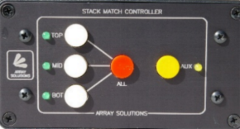 The PB-3 Stack Match controller is a replacement for the rotary switch
Stack Match controller. It features pushbutton switches for easy antenna
selection and has an Auxiliary output that may be used for phase control
or any other purpose that requires +12vdc to activate. It is a component
of the ShackLAN product line and as such can be fully remotely
controlled via computer with our ShackLAN Control Center software. All
outputs are switched with relay contacts for maximum reliability and
power for the external switching unit may be applied from a separate
power source to provide maximum isolation from the ShackLAN network.
There is also a PTT input to allow different stack configurations for
transmit and receive.
The PB-3 Stack Match controller is a replacement for the rotary switch
Stack Match controller. It features pushbutton switches for easy antenna
selection and has an Auxiliary output that may be used for phase control
or any other purpose that requires +12vdc to activate. It is a component
of the ShackLAN product line and as such can be fully remotely
controlled via computer with our ShackLAN Control Center software. All
outputs are switched with relay contacts for maximum reliability and
power for the external switching unit may be applied from a separate
power source to provide maximum isolation from the ShackLAN network.
There is also a PTT input to allow different stack configurations for
transmit and receive.
Up to four PB-3 controllers may be used on the ShackLAN network.
Configuration is simple using pushbutton switches on the front panel.
The PB-3 has two operating modes to suit your operating preference. The
default mode is push-on/push-off for antenna selection and the other is
direct antenna selection.
Installation
Standard power and network connections are the same in all ShackLAN units and is located here.
Isolated switch power
The PB-3 controller may be configured to use a separate power
source for the remote switch unit to isolate the remote switch unit
power from other units on the ShackLAN network. This is recommended if
you are in a lightning prone area. This feature requires power to the
controller be supplied via the ShackLAN network from other units.
Isolate the power by opening the power connection between the 2.1mm
power jack and the modular network connectors using the following
procedure:
Older Units:
1 - Remove the rear panel and slide the control board far enough out of
the case to expose the black relays.
2 - Cut the two small wire jumpers located behind the PTT jack to the
right of the relays.
3 - Slide the control board fully into the case.
4 - Install the rear panel.
Later units:
1 - Remove the rear panel and slide the control board far enough out of
the case to expose the black relays.
2 - Move the two small jumper blocks located behind the PTT jack to the
right of the relays to the EXT position.
3 - Slide the control board fully into the case.
4 - Install the rear panel.
Connect the isolated power source to the 2.1mm power jack. Center pin is positive. The supplied power cable may be used and the wire with the white tracer is positive and the solid black wire is ground.
Remote switch connections
Connections to the remote switch unit are made using the green
6-wire terminal plug on older units and the green screw terminal
connector on later units.. The basic Stack Match 2 requires four wire
connections. Add an additional wire each for phase switching and an
auxiliary function. Connections assume that antenna 1 is the top antenna
and from the rear panel are:
IN - Connect to IN terminal on remote unit
3 - Connect to #3 terminal on remote unit
2 - Connect to #2 terminal on remote unit
1 - Connect to #1 terminal on remote unit
G - Connect to GND terminal on remote unit
A - Auxiliary control output for any purpose requiring +12vdc when
enabled (optional)
PTT input (optional)
Connect a cable from the PTT input to the PTT output on the radio if you wish to have separate antenna configurations for transmit and receive or to prevent antenna switching during transmit periods. Ground this input to activate. You will need a "Y" adapter if you are using an amplifier.
Configuration
Unit ID (network address)
If you are using multiple PB-3 controllers in your station and
want computer or remote control ability you must set each controller to
a unique address. This is down with front panel switches by holding in
the ALL pushbutton while pressing one of the other pushbuttons and then
releasing both pushbuttons. The factory default is Unit #1. Unit ID is
set as follows:
PB-3 #1 = ALL + TOP
PB-3 #2 = ALL + MID
PB-3 #3 = ALL + BOT
PB-3 #4 = ALL + AUX
The controller will blink the LED next to the pushbutton three times to
indicate the unit ID.
Operating mode
The default operating mode (Mode 1) is Push-On/Push-Off. The
alternate mode (Mode 2) is direct selection. This mode directly selects
the antenna whose button is pressed. Multiple antennas are selected by
simultaneously pressing the buttons for the desired antennas. Switch
between the two modes by pressing and holding the AUX button longer than
two seconds. Upon releasing the button the current mode will be
indicated by flashing two LEDs as follows:
Mode 1 = TOP + AUX LEDs (Push-On/Push-Off mode)
Mode 2 = MID + AUX LEDs (Direct selection mode)
Operation
Power up
On power up the PB-3 Controller will scan thru the four LED indicators and then flash one of them three times to indicate the unit ID. The controller is now ready for use.
Antenna selection Mode 1
In Mode 1 the antenna buttons toggle the antenna selection. This is the simplest mode of operation. Pressing one of the antenna buttons will alternate between adding and removing that antenna from the stack. Note that the controller will not allow you to unselect all antennas. All antennas may be quickly selected using the ALL button.
Antenna selection Mode 2
In Mode 2 the antenna buttons directly select antennas. Pressing the TOP button will select only the top antenna. Same for MID and BOT buttons. To select two antennas you must press buttons for both antennas simultaneously. All three antennas are easily selected with the ALL button.
TX antenna configuration
The PB-3 has the ability to switch to a different antenna
configuration for transmitting. Set the transmit configuration as in
normal operation and then press and hold the ALL button for longer than
two seconds to save the transmit configuration. The controller will
flash the antenna LEDs to indicate success. Invalid configurations are
indicated by flashing the AUX LED.
The PB-3 will now use this configuration whenever the PTT input is
active.