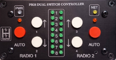
PB-28 Dual Switch Controller
Order PB-28 Controller - $169
Introduction
 The PB-28 is a dual radio antenna switch controller that offers the
simplicity of pushbutton operation. Each half of the PB-28 may be
independently configured as radio 1 to 4. For larger stations, this
controller may be configured to control one of up to four switches. In
Auto mode the PB-28 will indicate the antenna selected by one of the
Bandmaster series band decoders. The PB-28 has a USB connection that
allows for full control from software and also gives full access to all
devices on the ShackLAN network.
The PB-28 is a dual radio antenna switch controller that offers the
simplicity of pushbutton operation. Each half of the PB-28 may be
independently configured as radio 1 to 4. For larger stations, this
controller may be configured to control one of up to four switches. In
Auto mode the PB-28 will indicate the antenna selected by one of the
Bandmaster series band decoders. The PB-28 has a USB connection that
allows for full control from software and also gives full access to all
devices on the ShackLAN network.
Installation
Switch and Power connections
Connecting the PB-28 Controller to the antenna switch is done via the green 4-pin connector on the rear panel. The mating plug has screw terminals to simplify connecting the control cable. A 12 volts power source may be connected to either the 2.1mm power jack (center pin positive) or to the green switch connector. Information on wiring the switch connector is here.
Connecting to other ShackLAN devices
The PB-28 Controller may be connected to other Shacklan devices such as band decoders, stack controllers, etc. Connection to other devices may be made using the RJ-12 (modular) jacks using 6-wire modular cables. For older devices, you may connect to them using the green switch connector by connecting the other devices in parallel with the switch connections.
Configuration
Radio number
Each half of the PB-28 operates independently and each half may be assigned its own radio number. For stations using 2x8 switches (2 radios) the factory default of radios 1 and 2 should be sufficient. Assigning the radio numbers is done using the front panel pushbutton switches. Set the radio numbers by pressing and holding the left AUTO button along with the buttons for the desired radio numbers for at least two seconds. These buttons are labeled 1 thru 4. When the buttons are released the PB-28 will flash the configuration on the green antenna LEDs. When selecting two radio numbers the lower number is the left side (Radio 1) and the higher number is the right side (Radio 2). For multiple radio setups where two controllers are in use each controller may be configured to control only one radio in the antenna switch. This is done by pressing the left AUTO button and the button for the desired radio number for at least two seconds. This radio will be controlled by the left side (Radio 1) and the right side (Radio 2) will be unused.
Switch number
The PB-28 may be configured to control one of up to four antenna switches. The factory default is Switch #1 and this setting should not be changed for stations with a single antenna switch. For larger stations with multiple switches set the switch address by pressing the right AUTO button and the button for the switch address (1-4) for at least 2 seconds. When the buttons are released the PB-28 will flash the configuration on the green antenna LEDs.
Operation
The basics
Operating the PB-28 is a simple process. Manually select the desired antenna by pressing the up or down buttons until the desired antenna is selected. The green antenna LEDs are controlled by data from the switch and not the pushbuttons so a slight delay is normal. This verifys the switch received the command and has selected the desired antenna.Press the AUTO button to allow one of the Band Master series band decoders to automatically select antennas.
Fault indications
A "No Antenna Fault" is indicated by flashing
the orange AUTO LED for a particular radio. This is primarily a
warning that no antenna is currently selected. A "Communications
Fault" is indicated by flashing antennas LEDs 4 and 6 for both
radios. This indicates loss of communication between the PB-28 and
the antenna switch. The primary cause of this fault is a loose wire
in one of the connecters or a damaged control cable.