
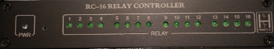
RC-16 Relay Controller
Order RC-16 Relay Controller - $199
 *
16 relay contact outputs
*
16 relay contact outputs
* Relay contacts can swith to either ground or up to 4 different voltage
sources
* 8 antenna configurations per band for up to 4 radios plus RX antennas
* 12 bands plus 8 custom frequency segments
* Fuse protected against reverse power and short circuits
* Anodized aluminum enclosure with laser engraved panels
* Custom panel labelling available
The Hamation ShackLAN RC-16 Relay Controller provides an elegant
solution to automate your existing remote antenna switches, such as
SixPaks, StackMatch, 4-squares, etc with the ShackLAN control system.
The RC-16 provides sixteen separate relay contact outputs that can
switch to ground or up to 4 different voltage sources. You may have
different relay configurations for multiple radios and up to eight
antenna configurations per band. It may also be used to automate RX
antenna switching, such as beverages or K9AY loop systems. Each antenna
macro may use any combination of outputs. Output connectors are
pluggable screw terminal connectors to allow easy connection of your
control cables. The unit is fused for protection against reverse polarity
power and short circuits on the outputs.
Installation
If you want a navigation menu for your side column that looks like the one on thesitewizard.com, you can generate your own and customize it, with the Navigation Menu Wizard. It's free, just like the Layout Wizard that you used to create this.
| ADDR | SW1 | SW2 | SW3 | SW4 |
| 1 | On | Off | Off | Off |
| 2 | Off | On | Off | Off |
| 3 | On | On | Off | Off |
| 4 | Off | Off | On | Off |
| 5 | On | Off | On | Off |
| 6 | Off | On | On | Off |
| 7 | On | On | On | Off |
| 8 | Off | Off | Off | On |
Network address
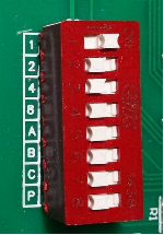 The first step is to set the address of the relay driver. The factory
setting is unit #1. All ShackLAN relay controllers in your system must
have a different address. If you have only a single unit in you system
you may use the factory default setting and skip this step. DIP switches
1 thru 4 are weighted 1,2,4,8. The address is determined by adding the
numbers for each switch in the On position. For example. if you have
switches 1 and 3 on the address would be #5. Switches A, B, C and P
should be in the Off position. Switch positions for each address are
shown in the table. The photo at the right shows address #1 selected.
The first step is to set the address of the relay driver. The factory
setting is unit #1. All ShackLAN relay controllers in your system must
have a different address. If you have only a single unit in you system
you may use the factory default setting and skip this step. DIP switches
1 thru 4 are weighted 1,2,4,8. The address is determined by adding the
numbers for each switch in the On position. For example. if you have
switches 1 and 3 on the address would be #5. Switches A, B, C and P
should be in the Off position. Switch positions for each address are
shown in the table. The photo at the right shows address #1 selected.
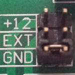
Relay common selectionThe RC-16 has 16 relays divided into 4 groups of 4. Each group of 4 relays has a common connection. This common connection may be selected, when a relay is activated, to switch to ground, supply 12v or supply an externally applied voltage. These selections are made using jumper pins in the unit. |
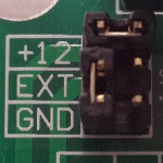 Supplies 12vdc when activated. "C" pin is ground. (Factory default selection) |
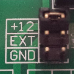 Supplies 12vdc when activated. "C" pin is not connected. |
| The jumpers for each group is located behind the corresponding relay connector. The factory default is to provide 12vdc when the relays are activated and should cover most installations. To change the common selection, remove the 4 screws from the rear panel and slide the board out far enough to access the jumpers. Shown to the right are 4 selection options. |
 Switches to ground when activated. "C" pin is not connected. |
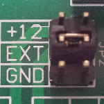 Connects to the power source on the "C" pin |
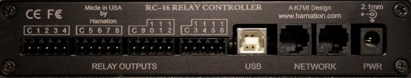
Power and network connections
The first step to connect the RC-16 to your system is to connect it to the network. Instructions for wiring the network connector are here. Either network connector may be used as they are in parallel. It is recommended that the Shacklan power be applied to the RC-16 and distributed to other devices via the Shacklan network connection.
Relay connections
Relay connections are made via the pluggable 5-pin connectors. No soldering is required. Each connector has outputs for 4 relays plus a pin for the common connection for that group of 4 relays. Attach the control wires by inserting them into the holes in the connector plug and tightening the screw to secure them.
USB connection
The USB connection may be connected to your PC and used to configure the unit and update firmware. It may also be used to control all other devices on the ShackLAN network.
Configuration
Before you begin
You will need to download and run the ShackLAN Control Center software before you can configure and operate the RC-16 Relay Controllers.
Antenna macro names
This step is optional but if you have more than one antenna on a band it is highly recommended. If this has not been done previously, such as configuring one of the Shacklan antenna switches, instructions for naming the macros is here.
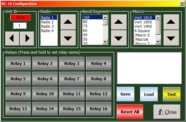
Naming the relay outputs
This step is also optional but is highly recommended as it will make the relay configuration much easier. Open the Relay Controller Configuration window by pressing the gear icon in the main Control Center window and then press then Relay Controller button in the Setup window. Start by setting the address of the relay driver you want to configure. You do not need to be connected to the RC-16 to name the relays. Press and hold for a few seconds on each relay button and enter a description name for that relay. These names are saved for each relay driver address. This will make the configuration process go a lot smoother.
Establish communications
Configuration may be done via a USB connection directly to the
Relay Controller or any ShackLAN unit as long as that unit is connected
to the network. You first need to
establish communication with the network.
The next step is to establish communications with the Relay Controller
you wish to configure. Select the address in the Unit ID box and
wait for the RC-16 to connect. You are now ready to start
configuring the unit.
Assigning relay outputs to the macros
Now on to configuring the macros (the actual mapping of relay
outputs to the antenna selections). You must be connected to the relay
driver before you can start this process. First, be sure you have set up
the ShackLAN Network Communications
and that the Control Center is communicating with the ShackLAN network.
Select the Radio and Band you wish to configure and wait for the "Data
received" message to appear. This confirms the current configuration for
this Radio and Band has been downloaded from the relay driver. Press the
Load button if the current data does not load automatically. The macro
buttons should also show the names you have given each macro (antenna
selection). If these names do not appear, be sure you entered the Macro
names for this band.
1 - Click on the button in the Macro panel for the macro (selection) you
wish to configure.
2 - Select the desired relays in the Selected Relays panel. These
buttons are push on/push off.
3 - Repeat steps 2 and 3 for each macro (selection) for this radio and
band.
4 - Click on the Save button when finished with each radio/band
combination to save to configuration to the RC-16 and wait for the
message saying the update was successful.
Repeat steps 1 thru 5 for each radio/band combination.\
Configuring the frequency segments
The frequency segment function of the relay controllers can
used to automatically control matching networks, primarily on low band
antennas. These segments should NOT be used to select an antenna, only
for control of matching networks. Use the band configurations for
antenna selection. Start by selecting the segment in the Band/ Segment
box and then press the Load button to load the current segment settings
if it does not automatically load. There are eight frequency segments
you can configure to your frequency preferences. Set the frequency range
of a segment by entering the upper and lower frequencies in the
indicated fields. Be sure to enter the frequency in KHz (no decimal
points). Press the Save button to save your frequency settings. Wait for
the message that the update was successful. Do this for each segment you
intend to use in your system. Configuring the relay outputs for each
Macro in a segment is identical to setting the relay outputs for each
band, the only difference is you select a segment instead of a band.
There are eight macros available for each segment but you would normally
use the same macro that selects the antenna used with the matching
network. Press the Save button after configuring the relays for each
segment and wait for the message that the update was successful.