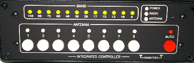
IC-8 Integrated Controller
Order IC-8 Controller - $249
 * Jumper free configuration
* RS-232, TTL and CI-V interfaces
* Configurable band limits
* Built-in USB interface
* Set default antenna per band
* Shows antennas used by all radios
* Amplifier protection when no antenna selected
* Field upgradeable firmware
* Anodized aluminum case
* Laser engraved panels
Introduction
The ShackLAN Integrated Controller has many advanced features not found
on the traditional antenna switch controller or band decoder. The
built-in band decoder is the heart of a ShackLAN antenna control system.
It is responsible for obtaining band information from the radio and
broadcasting the band and frequency data over the entire ShackLAN
network.
The IC-8 Integrated Controller combines all the features of the
Bandmaster series of decoders into an intelligent antenna switch
controller. It can operate in Auto mode which selects antennas based on
the band/frequency from the radio. It also gives to the ability to
manually select antennas. Selection of multiple antennas simultaneously
is possible by simply pressing multiple buttons at the same time. The
LED displays show the current band and antenna selection. It also
indicates antennas in use by a other radios as well as status of the
data connection to the radio and antenna switch. Another feature is
built-in amplifier protection system. This system will open the PTT
connection from the radio to the amplifier when no antennas are
connected, thus preventing the amplifier from keying when no antenna is
present.
Installation Part 1
Before you begin
Installing and configuring the IC-8 Integrated Controller is a simple process which involves connecting the unit to your computer and the ShackLAN network, setting the radio configuration and then connecting the decoder to your radio and any logging software. Optionally, you can route the amplifier PTT line through the controller for amplifier protection if no antenna is connected. Please DO NOT CONNECT YOUR RADIO to the unit until after the radio configuration has been done. You must configure the decoder before connecting the radio. Installation steps are listed below.
Switch and power connections
The first step in the installation of the decoder is to connect the unit to the ShackLAN network and power, if necessary. Power may be supplied thru the power jack or via the NET 1 connector. Instructions for the network and power connections are here. NET 1 is used to connect to the antenna switch and older ShackLAN devices. NET 2 is used to interconnect with other ShackLAN compatible devices. The two NET connectors are in parallel.
USB connection
The USB connector is used to transfer data to and from the radio to your computer using a standard USB cable. It is also used to update the firmware. The USB interface uses the popular FTDI chip and drivers and most computers already have the driver installed and the USB driver should automatically install itself. If it does not, drivers can be downloaded at https://ftdichip.com/drivers/. It is recommended you update the default USB virtual port settings for best performance. At this time you should power up the controller and the LED test will light each LED in sequence. You are now ready to configure your decoder.